
What is a gas booster pump and how does it work?
A gas booster pump is a device that takes a gas already under pressure and raises it to a higher level in a controlled manner without contaminating the gas in the process. It is used to transfer gases between tanks, charge high-pressure cylinders, recover residual gas from partially empty bottles, feed fuel cell systems or complete refueling operations with hydrogen, nitrogen, helium and other industrial and specialty gases.
Unlike a conventional compressor, which draws gas from atmospheric pressure and compresses it through a continuously driven mechanical motor, a gas booster pump works as a pressure intensifier. It starts with a gas that is already pressurized and increases its pressure using two mechanically coupled pistons of different surface areas. The difference in area between the two converts the force applied to the drive piston into a proportionally higher pressure on the gas. This principle is key to understanding why gas booster pumps can reach high pressures in compact units, and why they are widely used in applications where purity, precision and working pressure are critical.
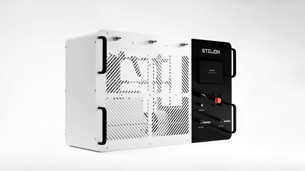
Electric driven gas booster pump
How does a gas booster pump work?
The working principle of a gas booster pump is based on the concept of pressure intensification through differential piston areas. The system uses two mechanically coupled pistons: a large-diameter piston (drive piston) and a smaller-diameter piston (compression piston). The area ratio between the two determines the compression ratio of the unit.
When a force acts on the drive piston, whether from compressed air, hydraulic oil or an electric motor, that force is transmitted entirely to the compression piston. Because the compression piston has a smaller surface area, the resulting pressure on the gas is proportionally higher. This is the same physical principle described by Pascal’s law, whereby pressure applied to a confined fluid is transmitted uniformly in all directions.
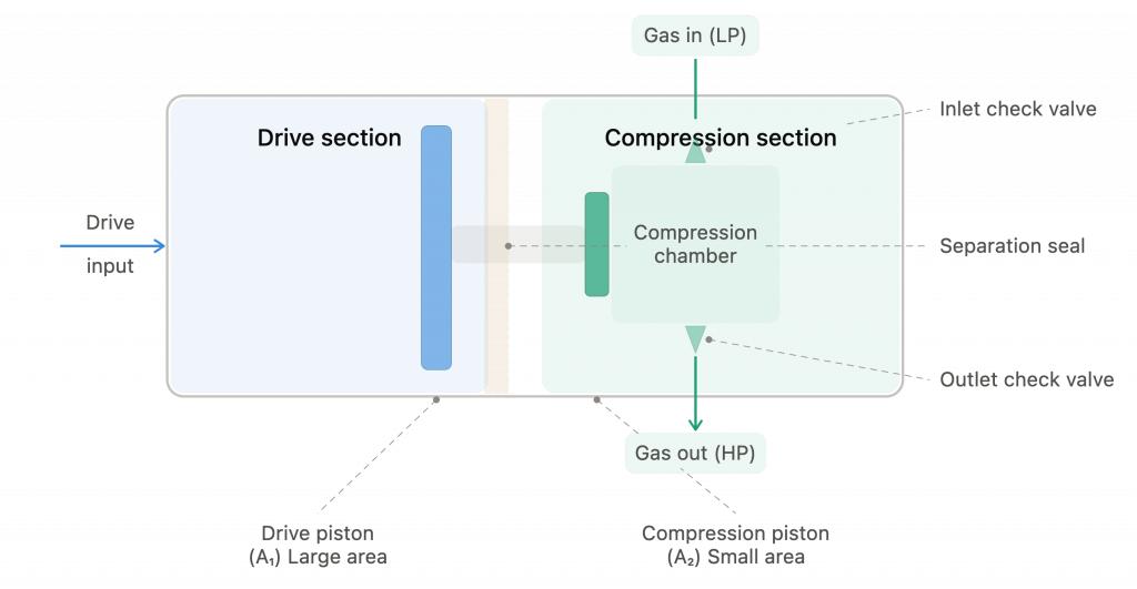
Main components of an electric gas booster pump
How is the compression ratio calculated?
The compression ratio is calculated by dividing the area of the drive piston by the area of the compression piston. If the drive piston has an area 30 times larger than the compression piston and is supplied with air at 6 bar, the theoretical gas output pressure will be 180 bar (6×30). In practice, friction losses and internal leakage reduce this value slightly, but the principle holds (Shi, Y. et al. (2007), Mathematical modeling of compression processes in air-driven boosters, Applied Thermal Engineering)
The operating cycle is reciprocating: the piston advances, compressing the gas in the high-pressure chamber, while check valves allow the compressed gas to exit. On the return stroke, fresh gas enters the chamber for the next cycle. In pneumatic boosters, this cycle repeats automatically thanks to a spool valve system that reverses the piston direction at the end of each stroke, with no external intervention required. The unit stops on its own when the outlet pressure reaches equilibrium with the driving force on the drive piston, a point known as stall pressure.
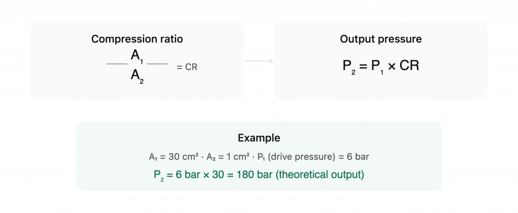
Gas booster compression ratio formula
Types of gas booster pumps by drive technology
There are three main drive technologies for gas booster pumps, each with distinct characteristics, advantages and limitations.
Pneumatic gas booster pump
The most widely used type historically. It uses compressed air as the power source to drive the piston. Its main advantage is simplicity. It requires no electricity at the point of use, incorporates no electronics and its maintenance is limited to the periodic replacement of seals and valves. Furthermore, the absence of electrical components makes it inherently suitable for explosive atmosphere environments (ATEX zones).
However, its energy chain is long and inefficient. The system is powered by an external air compressor, the air is transported through piping to the booster and, once there, drives the piston that compresses the gas. Energy is lost at every stage. According to a review published by Dindorf et al., the overall energy efficiency of a complete pneumatic system falls between 6% and 10% (Dindorf, R. et al. (2004), “A Review of Energy Overconsumption Reduction Methods in the Utilization Stage in Compressed Air Systems“). Added to this are high noise levels and the inability to digitally automate the charging process.
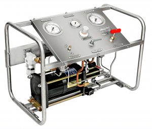
Pneumatic gas booster pump
Hydraulic gas booster pump
This type replaces compressed air with hydraulic oil as the driving medium. This enables higher forces and more stable flow rates, making it well suited for high-pressure applications and continuous operation.
The hydraulic booster incorporates a separation piece (distance piece) between the hydraulic section and the gas section that prevents cross-contamination, allowing gas purity to be maintained throughout compression. Its main limitation is installation complexity: it requires a hydraulic power unit (HPU), oil circuit, cooling system and a significantly larger footprint than the pneumatic or electric alternatives.
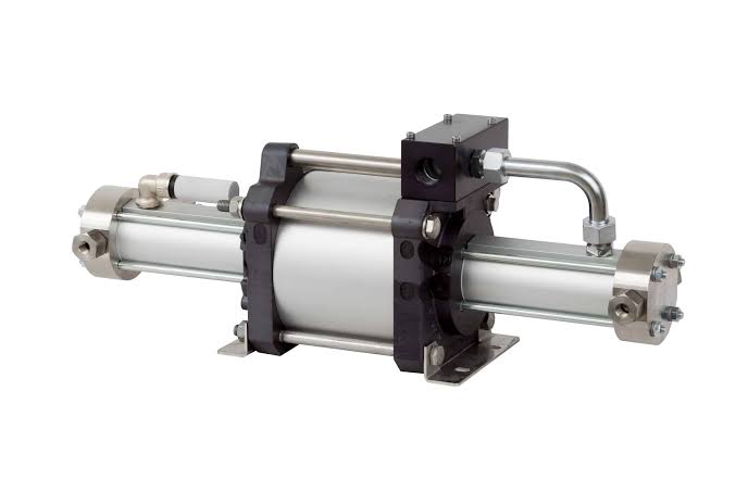
Hydraulic gas booster pump
Electric gas booster pump
This type replaces both compressed air and hydraulic oil with an electric motor coupled directly to the compression piston. As noted by John Crane in an analysis published in 2025, electrically driven gas booster pumps feature a shorter energy chain because they eliminate the leakage paths and transport losses inherent in pneumatic systems (John Crane (2025), “From Reliability to Electrification: Embracing Seal Gas Boosters for a Net Zero Future”)
This efficiency in energy transmission results in lower consumption, less heat generation and significantly reduced noise levels. Additionally, electric drive technology opens the door to integrating digital control systems, charging cycle automation and real-time monitoring, capabilities that pneumatic and hydraulic systems cannot offer natively.
An example of this evolution is STELION Booster Station, an electric gas booster pump developed by Hydros Power, which integrates a digital interface, automatic operating modes, energy monitoring and error management in a compact, European-certified and ATEX-compliant unit.
For a detailed comparison between pneumatic and electric technologies, see our article Electric vs pneumatic gas boosters: key differences and how to choose.
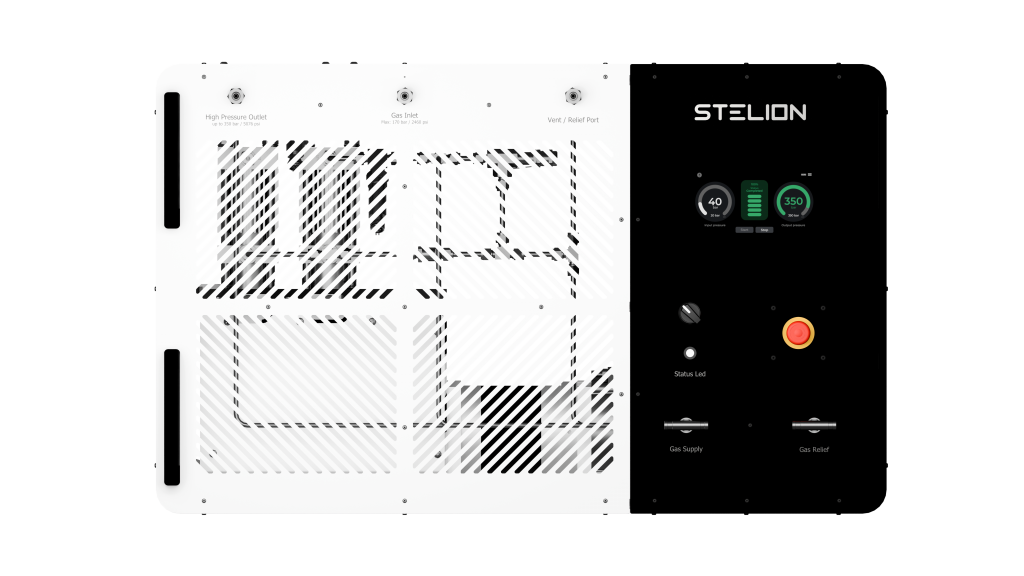
Electric gas booster pump – STELION Booster Station
Gas booster pump vs compressor: what is the difference?
This is one of the most common points of confusion in the industry, and it is worth clarifying, because while both share the general goal of raising gas pressure, they are fundamentally different pieces of equipment.
A conventional compressor draws gas at atmospheric pressure (or close to it) and compresses it through a continuously driven mechanism, piston, screw, diaphragm or centrifugal. It is designed to produce large volumes of compressed gas on a sustained basis and operates with its own motor, powered electrically or by combustion.
A gas booster pump, by contrast, starts with a gas that is already pressurized (typically between 2 and 200 bar, depending on the application) and raises it to a higher pressure. It doesn’t generate volume, it intensifies pressure. This makes it more compact, mechanically simpler and, in most configurations, oil-free in the compression chamber, ensuring the gas is not contaminated during the process.
The practical differences become especially apparent in areas such as gas purity and ease of installation. In many configurations, the gas booster pump keeps the drive section and the compression chamber physically separated, reducing the risk of gas contamination from oil or particulates. This is particularly relevant when working with hydrogen, oxygen or other high-purity gases. On top of this, the typically more compact architecture makes it easier to integrate into facilities where space is limited and reduces the auxiliary infrastructure required compared to larger industrial compression systems.
These characteristics explain why the gas booster pump is especially well suited when the objective is not to generate pressure from scratch, but to raise the pressure of a gas that is already available. Operations such as cylinder charging, gas transfer between tanks, feeding fuel cell systems or carrying out refueling operations can be addressed with a more compact solution specifically designed for this type of process.
Key applications of a gas booster pump
Gas booster pumps are used across a wide range of industrial and research sectors. One of the most common applications is high-pressure gas cylinder transfer and charging, where the booster recovers residual gas from partially empty bottles and transfers it at operating pressures, reducing waste and optimizing gas usage. This is, in fact, one of the original applications for which the first gas booster pumps were designed over 50 years ago.
In the hydrogen sector, gas booster pumps play a growing role in small-scale refueling stations, fuel cell supply, hydrogen delivery for laboratories and universities, and refueling of light vehicles, drones and UAV platforms.
Other applications include pressure testing and component validation in the aerospace and automotive industries, specialty gas supply in the semiconductor industry, pressurization systems on offshore oil and gas platforms, and gas feed in manufacturing processes that require controlled pressures.

Hydrogen-powered drone, one of the key applications for gas booster pump refueling
What gases can a gas booster pump compress?
Gas booster pumps are designed to work with virtually any industrial or specialty gas, including hydrogen (H2), nitrogen (N2), helium (He), argon (Ar), oxygen (O2), carbon dioxide (CO2), compressed natural gas (CNG) and application-specific process gases.
However, not all gases are treated equally. Hydrogen, for example, has specific material compatibility requirements due to the phenomenon of hydrogen embrittlement, a process in which hydrogen atoms penetrate the crystalline structure of certain metals and cause a progressive loss of ductility and mechanical strength. This means that gas booster pumps intended for hydrogen service must use materials certified for this purpose, and that seals, valves and internal components must be specifically designed to prevent degradation.
Oxygen, on the other hand, demands an extreme level of cleanliness in the compression chamber: any trace of oil or hydrocarbons in contact with oxygen at high pressure can cause spontaneous ignition. Boosters intended for oxygen service undergo special cleaning processes (oxygen cleaning) to ensure the complete absence of contaminants.
These compatibility requirements mean that selecting a gas booster pump goes beyond pressure and flow rate. The type of gas being handled is equally critical, and it is a factor frequently underestimated during the equipment specification phase.
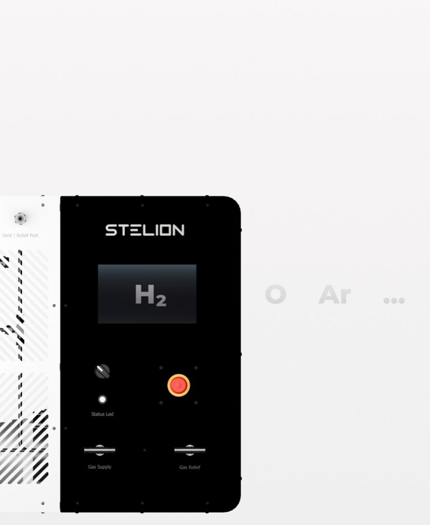
Gas booster pumps are compatible with hydrogen, nitrogen, helium, oxygen, argon and other industrial gases
In summary
A gas booster pump is a seemingly simple piece of equipment, but selecting the right one requires considering multiple factors: gas type, working pressures, frequency of use, installation environment, required certifications and the most suitable drive technology for each case.
In a context where hydrogen is driving demand for more efficient, more compact and more intelligent compression equipment, the gas booster pump is evolving from its original conception as a purely mechanical component toward a new generation of units with digital control, integrated automation and specific certifications to operate with the gases that will define the energy transition.
If you are exploring electric gas boosters for hydrogen or industrial gas applications, learn more about STELION Booster Station, its specifications and how it works.
Recent articles

Press contact
For press inquiries or additional information about Hydros Power and its hydrogen solutions, you can contact the team at:
Guillermo Megías Collado
guillermo.megias@hydros-pwr.com
+34 865 642 254